


IOL power calculation by means of a theoretical optical model uses corneal information in two ways. The first and most important is to quantify the optical performance of the cornea within the whole system. The second and less relevant is the contribution of the cornea to the prediction of the IOL position.
In this process, the cornea is characterized by one number: the keratometry (K) value, which is usually calculated from the measured mean anterior curvature radius of the central cornea. However, when the corneal anterior surface is irregular, one single number is insufficient to correctly model the corneal optics and, therefore, to accurately predict the power of the IOL that will provide the best focus.
CORNEAL OPTICS AND IOL FORMULAS
The central corneal shape is best described as an aspheric-toric surface with some irregularities. The main geometry can be fit with a biconic equation, where the curvature radius and conic constant (asphericity constant) of two orthogonal meridians characterize the shape. Irregularities that depart from this model are usually described with a Zernike polynomial expansion, in which each type of deformation is quantified with a coefficient.1
AT A GLANCE
• Correct diagnosis of corneal irregularity is essential to avoid calculation errors.
• Good quality measurements are necessary as a starting point for any IOL power calculation.
• Thick-lens ray tracing allows quantification of the impact of an irregular cornea on retinal imaging and helps in selecting the best IOL.
Despite this complexity, from the first IOL formulas described in the late 1960s by Fyodorov and Gernet to more recent ones such as the Holladay 2 and Olsen, the cornea has been characterized solely by the K value. This is the paraxial corneal power, calculated with an arbitrary corneal index of refraction to account for the power of the unmeasured posterior corneal surface. The K value assumes the cornea to be spherical and to maintain a certain proportion between the anterior and posterior curvatures. This approach achieves clinically acceptable accuracy in regular corneas. This means that, in normal eyes, corneal higher-order aberrations (HOAs) do not play a relevant role and can be neglected for refraction prediction and that variance in the anterior-to-posterior corneal curvature ratio is low. This has been demonstrated in ray-tracing models as well.2
All theoretical vergence formulas in use today (eg, Hoffer Q, Holladay 1 and 2, SRK/T, and Haigis) are paraxial by definition and perform under a thin-lens assumption. In recent years, some newer formulas including Okulix (Tedics Peric & Jöher) and PhacoOptics (IOL Innovations), which use thick-lens models to perform ray-tracing calculations, have come to market. The cornea is modeled as a second-order surface, and spherical aberration is therefore computed.
Some instruments now incorporate calculation software using the measured parameters. For example, the Sirius tomographer (CSO) uses a pseudophakic thick-lens model to perform ray-tracing calculations and a proprietary algorithm to predict IOL position. One important issue with these thick-lens formulas is that the posterior corneal radius is not assumed but can be input from measurements.
IRREGULAR CORNEAS
Irregular corneas violate the assumptions that allow IOL power calculations based on K values, as these corneas can show high levels of HOAs and the anterior-to-posterior corneal curvature ratio can be abnormal. Moreover, the precision of measurements is usually affected in these corneas. Irregular corneas are most often seen after corneal surgery and in eyes with keratoconus, corneal scars, or dry eye.
Correct diagnosis of corneal irregularity is essential to avoid calculation errors and to determine the best calculation process. The problem is first categorized by taking a careful clinical history and examining the corneal topography pattern, which will help to determine the type of pathology and/or previous corneal surgery. The optical significance of any corneal irregularity should be clinically tested using rigid gas permeable contact lens over-refraction if the cataract is not dense. Corneal HOAs are quantified using a corneal tomographer (Scheimpflug or OCT). The mean HOA root-mean-square of a regular cornea for a 6-mm pupil is around 0.40 ±0.15 µm.3 Any number outside of normal bounds indicates that the cornea is irregular. High levels of spherical aberration and coma are usually found after laser refractive surgery or RK. In keratoconus, coma is the main HOA responsible for optical degradation. Pupillometry is essential to understand how significant the corneal aberrations are for each eye. The smaller the pupil, the lower the effect of corneal aberrations on visual function.
CASE EXAMPLE
A 62-year-old woman presented with a history of LASIK in her right eye, performed 15 years earlier. The patient had poor visual quality due to decentration. At the time of presentation, her CDVA was 0.30 (Snellen decimal) OD, and she had a +3 nuclear cataract.
Corneal topography showed a decentered laser myopic ablation with high higher-order aberrations, especially coma (Figures 1 and 2). IOL calculation for emmetropia was 23.50 D with the ASCRS calculator and 24.50 D with PhacoOptics (IOL Innovations), inputting the posterior K value from Scheimpflug measurement.
Ray-tracing calculation from corneal topography with Sirius software (CSO) estimated that visual quality was a little better with a 26.50 D lens than with a 25.00 D lens, even leaving the spherical equivalent refraction more myopic (-1.22 vs -0.10 D; Figures 3 and 4). A 26.00 D IOL was implanted. Residual spherical equivalent refraction was -1.00 D, and CDVA was 0.70.
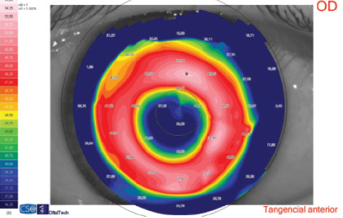
Figure 1. Corneal topography. The simulated keratometry reading was 38.75 D. Significant decentration can be seen in the tangential map.
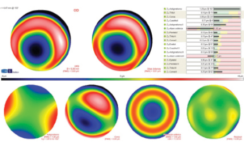
Figure 2. Corneal aberrometry for a 6-mm pupil. Third-order coma is the highest HOA value.
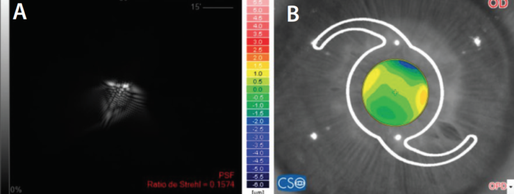
Figure 3. Retinal image of the point spread function (PSF; A) and OPD (B) in an eye with a 3-mm pupil; with a 25.00 D IOL, refractive prediction (spherical equivalent) is -0.19 D. Strehl ratio is 0.16.
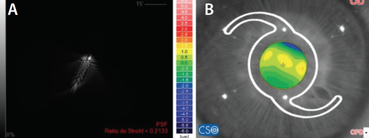
Figure 4. Retinal image of the PSF (A) and OPD (B) in the same eye; with a 26.50 D IOL, refractive prediction (spherical equivalent) is -1.22 D. Strehl ratio is 0.21.
Another important figure is the corneal anterior-to-posterior radius ratio. In normal corneas, this ratio is 1.21 ±0.02.4 However, each 0.01 change translates to a 0.05 D error using the standard keratometric index of refraction of 1.3375. Significant changes in the ratio are normally found after corneal laser surgery or RK. Curiously, myopic LASIK and PRK shift the number upward, whereas myopic RK normally drives it downward, as the posterior cornea flattens.
IOL POWER CALCULATION
Good quality measurements are necessary as a starting point for any IOL power calculation. Optic axiometry of all intraocular distances allows a precise estimation of the IOL position using modern formulas. The cornea should be measured at least three times to ensure repeatability. Agreement of the anterior radii between autokeratometry and Scheimpflug tomography should also be confirmed. The latter will also provide the posterior radii and corneal aberrometry.
After LASIK and PRK. The main problem in post-LASIK and post-PRK eyes is the anterior-to-posterior ratio change due to these surgeries’ modifications of only the anterior radius. Spherical aberration can be an issue if the correction was high, especially for old ablation profiles. Estimation of IOL position is driven to error if the formula uses the cornea as a predictor.
These cases can be calculated with vergence formulas that use a double-K method for correct IOL position calculation and/or use regression statistics to correct the anterior-to-posterior ratio issue. These include the double-K SRK/T and Holladay, Barrett True K, Haigis L, and Shammas PL formulas.5 Another option is to use a formula that adds the calculation of the effect of the spherical aberration from central corneal asphericity and that allows input of the measured posterior corneal radius; such formulas include the PhacoOptics and Okulix. Another approach that has shown good results is the use of IOL calculations based on intraoperative aberrometry.6
One advantage of IOL calculations in post-LASIK and post-PRK eyes is that experience is vast, and data-based statistics can help fine-tune any method.
After RK. In post-RK eyes, the anterior radii are flatter than normal. Therefore, to start with, error should be avoided by choosing a double-K method or a formula that does not use the cornea as a predictor of IOL positioning. However, the main difference in post-RK eyes compared with post-LASIK and post-PRK eyes is that the posterior cornea is flattened, producing a different anterior-to-posterior ratio. Camellin et al7 found this value to be 1.12 ±0.07 in post-RK eyes.
Therefore, the measured K value in these eyes will underestimate the actual corneal power. Variance of this ratio is much higher than in post-laser eyes, likely due to the manual nature of the surgery. This introduces greater chance for error if any function is used to estimate the posterior radius from the anterior radius. Fortunately, the anterior-to-posterior corneal curvature ratio in RK is not far from that in normal eyes, so the related amount of error is not large.
Another relevant consequence in post-RK eyes is that, if a formula that calculates the pre-RK K value from the measured posterior radius based on LASIK and PRK data is used, a large error will occur, as the calculated K value will be even lower. Thus, the best approach is to measure both the anterior and posterior radii and to use a formula or software that models a thick cornea, such as PhacoOptics, Okulix, or Sirius.
Decentered corneal refractive surgery. A decentered LASIK, PRK, or RK will impair the optical performance of the cornea, adding more HOAs, mainly coma, to the spherical aberration. Surface modeling goes beyond the second order in large decentrations, and there is a need for more complex models. The more aberrated the cornea, the more we should move from paraxial to exact optics. Even talking about postoperative refraction error is imprecise, as the patient can choose different lenses due to the multifocality within the decentered optical zone. (Power is a paraxial concept.)
In these cases, the central corneal data should be exported to software that performs exact ray tracing and allows calculation of image quality on the retina. PhacoOptics, Okulix, and Sirius software can import topography data and render an image that would be produced on the retina with different IOL powers. Another option for expert users is to export topographic data to optical software such as Zemax (Radiant Zemax) or Optics Software for Layout and Optimization (OSLO; Lambda Research). These programs can calculate different metrics to determine the best option. Inputs for curvature, thickness, and index of refraction of IOLs are needed with this approach.
Keratoconus. In keratoconic eyes, a similar problem of optical decentration exists, with one important difference: The posterior cornea steepens along with the anterior cornea, decreasing the anterior-to-posterior ratio. This causes the K value to overestimate the actual corneal net power. Another issue is the IOL position within the eye, which is more posterior than in normal eyes. Both factors shift the refractive prediction error toward hyperopia. This is why, in mild to moderate keratoconus, a regular vergence formula can be used, targeting for some myopia.
In moderate to severe cases, when multifocality within the pupil area is high, ray-tracing software should be used to select the best IOL power. If the user can change the IOL position within the model, it should be increased, as there is no algorithm specific for keratoconic eyes. If this is not possible, a simple alternative is to target a slightly myopic refraction.
CONCLUSION
Understanding the cornea’s role in IOL power calculation is important to avoid errors when corneal shape is abnormal. Newer formulas avoid the most common errors. Thick-lens ray tracing allows quantification of the impact of an irregular cornea on retinal imaging and helps in selecting the best IOL.
1. Navarro R. The optical design of the human eye: a critical review. J Optom. 2009;2:3-18.
2. Canovas C, Abenza S, Alcon E, et al. Effect of corneal aberrations on intraocular lens power calculations. J Cataract Refract Surg. 2012;38:1325-1332.
3. Read SA, Collins MJ, Iskander R, Davis BA. Corneal topography with Scheimpflug imaging and videokeratography: comparative study of normal eyes. J Cataract Refract Surg. 2009;35:1072-1081.
4. Aramberri J, Araiz L, Garcia A, et al. Dual versus single Scheimpflug camera for anterior segment analysis: precision and agreement. J Cataract Refract Surg. 2012;38(11):1934-1949.
5. Abulafia A, Hill WE, Koch DD et al. Accuracy of the Barrett True-K formula for intraocular lens power prediction after laser in situ keratomileusis or photorefractive keratectomy for myopia. J Cataract Refract Surg. 2016;42:363-369.
6. Ianchulev T, Hoffer KJ, Yoo SH, et al. Intraoperative refractive biometry for predicting intraocular lens power calculation after prior myopic refractive surgery. Ophthalmology. 2014;121:56-60.
7. Camellin M, Savini G, Hoffer KJ, et al. Scheimpflug camera measurement of anterior and posterior corneal curvature in eyes with previous radial keratotomy. J Refract Surg. 2012;28(4):275-279.
